The first step is to measure if the power supply is working. The time I started with the documentation of this website I have already done this step so I can explain in detail the problems and workarounds in a singe post.
The power supply consists of seven main supplies. However, several boards do have additional circuits (e.g. 78xx) to provide the required voltage for a particular need.
Getting ready
According to the service manual the measurement has to be done by switching to CD-Mode. However, to measure the board outside of the device more steps have to be done to enable the whole range of power supplies because the whole CD part gets disabled if the unit is not in CD-Mode. Page 734 in the service manual points out the necessary steps to overcome this behaviour.
Measurement of the different voltages
I measured the power supply of two units. For the moment I will keep the third device untouched. The results of the measurement have shown that all voltages are way too high. Whilst it is a non regulated power supply it was expected that they are higher, but the numbers are horrible:
- What should be 9V is 13.5V
- 12V => 16.8V
- 31V => 43V
Components are getting quite hot. Interesting is the note about the general condition in the service manual on page 734. It points out a valid input range of 220V +/-2% 50HZ. In the late 80ies Austria switched from 220V to 230V with +/-23V. So the voltage can be somewhere between 207V and 253V. Way too much, considering the input power during the measurement has been exactly 230V.
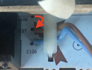
Luckily the build-in transformer has an option to handle input voltages of 240V. So I reconnected the connection pin of the on/off switch from C108 (Pin 5) to C107 (Pin 6). Finally the voltages where now much closer to the values in the service manual. Well, that was easy going…

Replacing capacitors
Of course replacing capacitors is often needed for vintage devices so I replaced all of them and measured the capacity of the old ones. They were a little bit off the reference value especially those with very high capacity made by Philips (the blue ones).
I ordered the component list accordingly to the service manual just to figure out that both of my boards are slightly different from the documentation. Might need to add the additional components and circuits later on. For now the work on the power supply is done. Voltage are more or less equal with the service manual and stable, thus ready to go ahead.
Since I have not got low ESR capacitors in the first place, I will come back again later to replace them again with some long life quality capacitors.