The idea
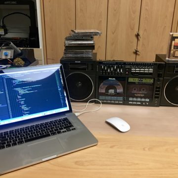
I do not know any other tape deck that can be programmed like a CD-Player. This always fascinated me. However, the user interface was a little bit limited and I never understood why I cannot jump two or more tracks ahead. By default the firmware supports to jump to the next and prior track. There are also some other limitations.
After I failed several times repairing the sound machine it was time to use the total Covid mayhem to learn and improve myself in electronics. On the first unit the tape deck was not working and CD-Player keys were blocked since they are controlled by the tape deck CPU. Quite soon after testing the CPU I noticed it is broken (not on other devices although the have shown the same issue).
The idea of replacing the CPU and update the firmware with functions I would think useful was born. To be aware of my lack of knowledge in this field – although I visited a higher school in electronics I was way from this field for more than 25 years – I know that I am ging to have increased costs and need multiple attempts to get it done. aNyway, I considering it as a hobby and it is allowed that a hobby can cost something…
The initial situation and challenges
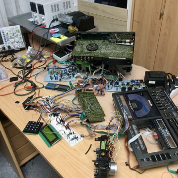
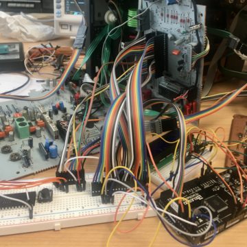
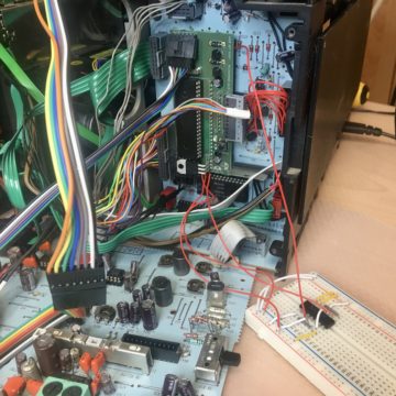
The very first approach was for testing purposes only. I used a common Arduino Mega connected with tons of cables. The goal was to learn how the mechanism is working and how sensors, relays and motors are working. After some unsuccessful tests I figured out the relays are not switching or to be more precise – not all the time. The issue is based on the different voltages used by the original CPU and the AT1284 used in the Arduino. The darlington circuit is designed for 6V but the AT1284 can only handle up to 5.5V. Of course I use 5V and do not want to reduce the life time of the AT1284. That means the resistors of the darlington circuit have to be recalculated.
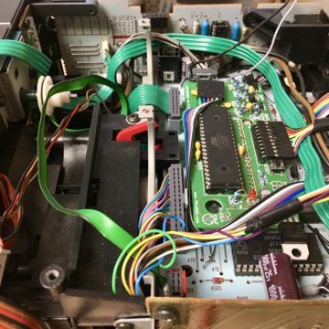
Since I am not a professional I have done some tests to figure out what values are working and enable the transistor to deliver the required current for the relays. Another objective was to have a plug and play replacement to avoid changing anything on the original PCB, except to replace the 40pin CPU with a socket.
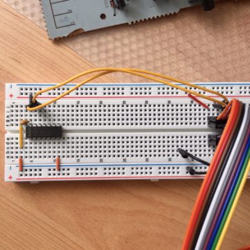
The clock for CD-Player CPU gets powered by the same oscillator as for the tape deck CPU. That means the internal circuit to power the oscillator of the original CPU has to be replaced. Whilst this is usually an inverter I successfully used an 74×04 inverter in my experimental board.
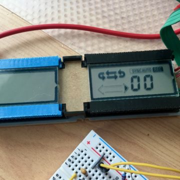
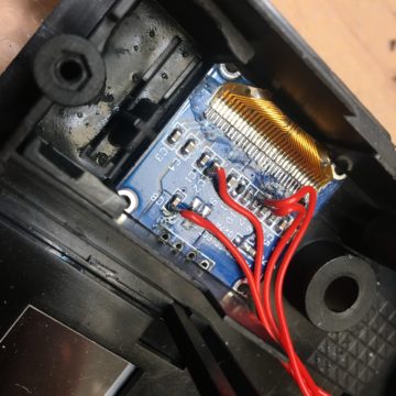
I also had to figure out how the LCD display gets addressed. It is just a serial connection with 32 segments and was done quite fast.
At the end it took a while to figure out to handle the mechanism and especially the timing. Sometimes I was lucky to get the idea of how a function works. Like the autoreverse function which I accidentally figured out when I tried to rewind the tape. It was a learning process and absolutely interesting. I would say this tape mechanism is a little masterpiece built by some genius.
Revision A
After some research I decided to go with the AT1284P CPU, a 40-pin DIP case which has the same flair as the original CPU. Besides this it is quite hard for me to handle small SMD parts. I might be too old, need a magnifier lamp and maybe one or two good old Scottish Whisky to get a steady hand…
To be able to use this kind of CPU I had to design a breakout board first which can be used to burn the boot loader with the help of a Arduino Mega. I am also going to add this project to the “modification” section.
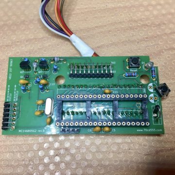
Now to get a little bit more professional I designed a PCB with Fritzing. It is free, easy to use and results can be ordered from Aisler in an uncomplicated way.
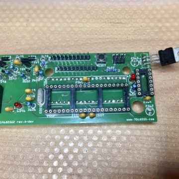
The design basically reflects the experimental boards:
- reduce 6V to 5V as a supply for the AT1284P
- an inverter that powers the oscillator
- the new darlington transistors have to provide enough current to switch the relays
- an interface to use a FT232 for data exchange
- a reset key and debug LED
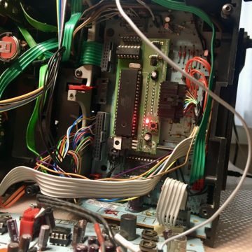
Revision A itself worked with the tape mechanism and I was able to continue debugging the new firmware. But the clock for the CD-Player was not working. After some time the clock stopped and only delivered 5V. I have done a lot of test but was not able to figure out why it was working on the experimental board and not on the PCB. As a result I decided to try another approach.
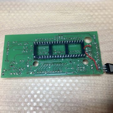
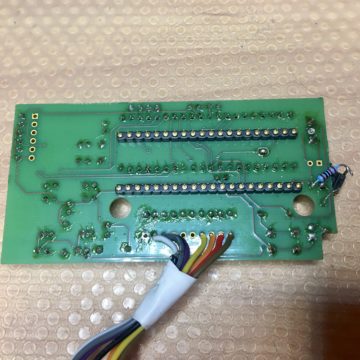
Another issue was that I forgot the cutouts for the motor driver. Whilst all other cutouts for underlaying capacitors and transistors where right in place I had to use a saw to get the PCB in place.
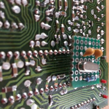
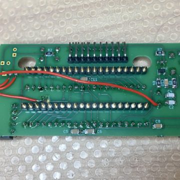
I ended up using a small circuit at the backside of the CD-Player CPU to power it with 4MHz.
Revision B
In this revision I removed the inverted which allowed to reduce the size of the board. The cut-out for the motor driver was still not huge enough and required again some “saw activities”.
Instead of the inverted I powered the clock for the CD-Player by the build-in timer of the AT1284P. This only give 1MHz instead of 5.8MHz but was enough to work. As alternative I added a backpack PCB for the 4MHz clock which can be put directly onto the CD-Player CPU. That was not the idea of plug & play that I had and I was not happy with that solution.
In this revision I also removed the LED which acted as data exchange control and the ISP connector. I finally found a good connector for the PCB since the socket I used before was only a huge work-around.
Revision C
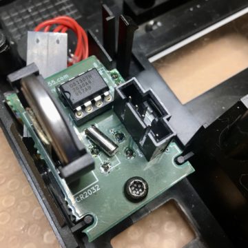
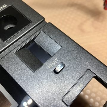
This revision never made it to an actual PCB since I had another idea – to build a digital counter. I used rev.B for tests and added the counter reset button “on the fly”.
Revision D
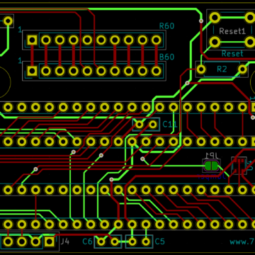
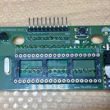
Now I moved to kiCAD since I found Fritzing limited and some bugs drove me absolutely crazy. So I had to learn how kiCAD is working but I am really satisfied how easy and fast you can build circuits and PCBs.
In the same step I decided to use 1206 SMD parts as Philips used in the Sound Machine.
It also powered the CD-Player clock with the bull int timer but as I had to figure out it was not stable and from time to time the CD-Player CPU hang.
The cut-outs are not good and I found connectors which I can use for the final revision
Revision E
Well this revision also never made it into real life. It contained some optimisations but when I was finished and right before I was ready to order I figured out how to power the clock for the CD-Player.
I successfully used revision D for additional tests with two D-FlipFlops as a divider for the 16Mhz to get 4MHz for the CD-Player. Unit #3 was running for hours without any issues which then lead me to the (hopefully) final design.
I have also done some unsuccessful tests with optical sensors to measure the tape position. That was an idea to improve the limited digital counter to get it more accurate. I need to continue my tests on this.
Revision F
The current revision. Since the clock for the CD-Player CPU was not working I added two D-FlipFlops to divide the 16MHz clock of the AT1284P into 4MHz to be in the range for the CD-Player CPU. This worked fine and I probably should have done this in the very beginning. But as I said it was a learning process for me.
There were some minor changes to the digital counter part on the cut-outs for the PCB.
