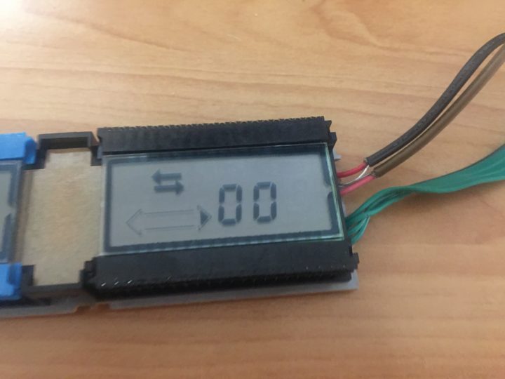
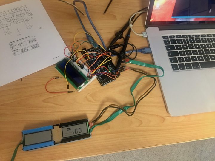
First step of replacing the tape deck CPU is to write a driver for the LCD display to be able to see what is going on. The display consist of two MM5452N, serial lcd drivers which are still available nowadays. Checking the display is also a good change to proof if the hardware is working and if that may caused the display to show all options.
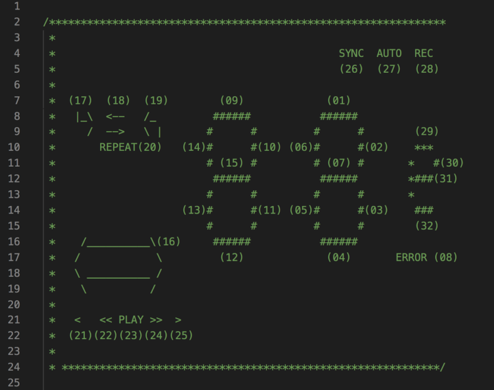
I dismantled the lcd part of one of the devices and connected them to the Arduino. I found that there are libraries out there for the MM5452 but unfortunately the where not working. However, they would handle a display with four segments which we do not have. There are only two segments and the other codes are used for displaying additional options like play, reverse, record and programming.
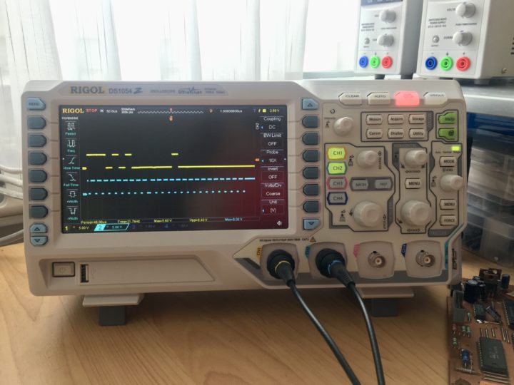
To write a serial communication is easy since we only need two pins, one data and one clock signal. According to the display driver’s data sheet we need to send one clock impulse to draw the MM5452 attention on the incoming data. The clock signal represents a short pulse to low.
void TDisplay::pulseClock()
{
  digitalWrite(PIN_DISPLAY_CLOCK, LOW);
  digitalWrite(PIN_DISPLAY_CLOCK, HIGH);
}
In a second step we need a variable large enough to hold the 32bits we need to tell the display what we want to see. A simple test reveals all the options. The routine itself is nothing special. The following listing also gives some room for improvement but is enough to test and learn how to address the device’s display.
  digitalWrite(PIN_DISPLAY_DATA, HIGH);
  pulseClock();

  long bit = 1;
  for (int x = 1; x <= segmentCount; x++) {

    if ((value & bit) != 0) {
      digitalWrite(PIN_DISPLAY_DATA, HIGH);
    }
    else {
      digitalWrite(PIN_DISPLAY_DATA, LOW);
    }
    bit = bit << 1;
    pulseClock();
  }


